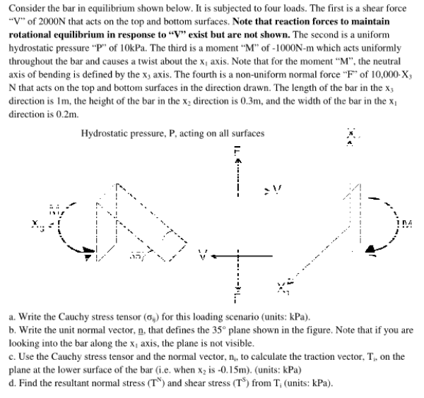
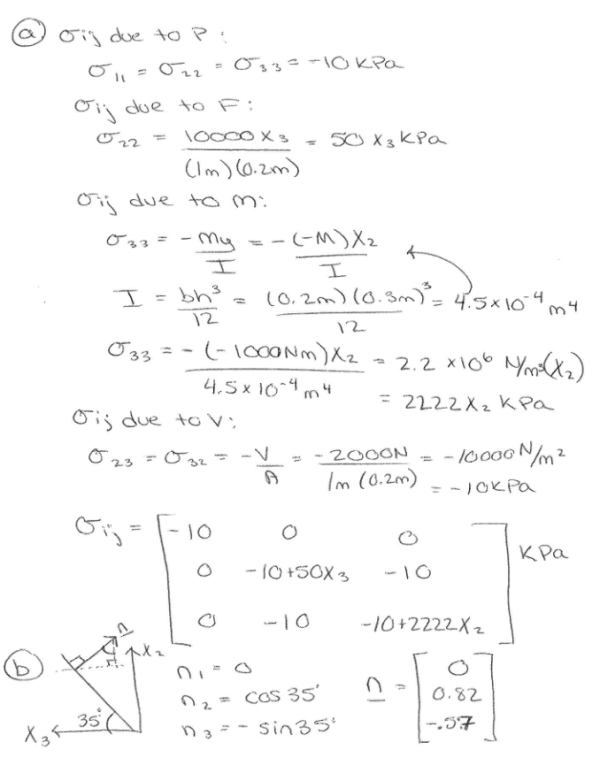
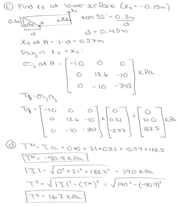
Consider the bar in equilibrium shown below. It is subjected to four loads. The first is a shear force of 2000 N that acts on the top and bottom surfaces. Note that reaction forces to maintain rotational equilibrium in response to V exist but are not shown. The second is a uniform hydrostatic pressure P of 10 kPa. The third is a moment M of -1000 Nm which acts uniformly throughout the bar and causes a twist about the x1 axis. Note that for the moment M, the neutral axis of bending is defined by the x3 axis. The fourth is a non uniform normal force F of 10000X3 N that acts on the top and bottom surfaces in the direction drawn. The length of the bar in the x3 direction is 1 m, the height of the bar in the x2 direction is 0.3 m, and the width of the bar in the x1 direction is 0.2 m. a) Write the Cauchy stess tensor for this loading scenario. b) Write the unit normal vector, n, that defines the 35 degree plane shown in the figure. Note that if you are looking into the bar along the x1 axis, the plane is not visible. c) Use the Cauchy stress tensor and the normal vector to calculate the traction vector T on the plane at the lower surface of the bar. d) Find the resultant normal stress and shear stress from T.
Highalphabet Home Page biomechanics biomechanics biomechaincs Page 1
Consider the bar in equilibrium shown below. It is subjected to four loads. The first is a shear force of 2000 N that acts on the top and bottom surfaces. Note that reaction forces to maintain rotational equilibrium in response to V exist but are not shown. The second is a uniform hydrostatic pressure P of 10 kPa. The third is a moment M of -1000 Nm which acts uniformly throughout the bar and causes a twist about the x1 axis. Note that for the moment M, the neutral axis of bending is defined by the x3 axis. The fourth is a non uniform normal force F of 10000X3 N that acts on the top and bottom surfaces in the direction drawn. The length of the bar in the x3 direction is 1 m, the height of the bar in the x2 direction is 0.3 m, and the width of the bar in the x1 direction is 0.2 m. a) Write the Cauchy stess tensor for this loading scenario. b) Write the unit normal vector, n, that defines the 35 degree plane shown in the figure. Note that if you are looking into the bar along the x1 axis, the plane is not visible. c) Use the Cauchy stress tensor and the normal vector to calculate the traction vector T on the plane at the lower surface of the bar. d) Find the resultant normal stress and shear stress from T.
biomechanics page 1 biomechanics biomechanics biomechanics biomechanics biomechanics biomechanics biomechanics biomechanics page 2