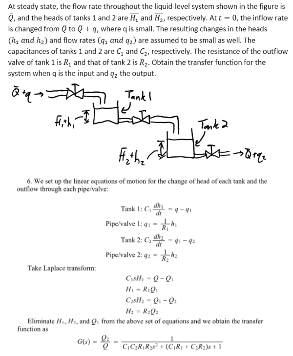
At steady state, the flow rate throughout the liquid-level system shown in the figure is Qbar, and the heads of tanks 1 and 2 are H1bar and H2bar, respectively. At t=0, the inflow rate is changed from Qbar to Qbar+q, where q is small. The resulting changes in the heads (h1 and h2) and flow rates (q1 and q2) are assumed to be small as well. The capacitances of tanks 1 and 2 are C1 and C2, respectively. The resistance of the outflow valve of tank 1 is R1 and that of tank 2 is R2. Obtain the transfer function for the system when q is the input and q2 the output.
Highalphabet Home Page dynamics dynamics System Dynamics Page 1
At steady state, the flow rate throughout the liquid-level system shown in the figure is Qbar, and the heads of tanks 1 and 2 are H1bar and H2bar, respectively. At t=0, the inflow rate is changed from Qbar to Qbar+q, where q is small. The resulting changes in the heads (h1 and h2) and flow rates (q1 and q2) are assumed to be small as well. The capacitances of tanks 1 and 2 are C1 and C2, respectively. The resistance of the outflow valve of tank 1 is R1 and that of tank 2 is R2. Obtain the transfer function for the system when q is the input and q2 the output.
System Dynamics Page 2 dynamics dynamics dynamics dynamics dynamics dynamics dynamics System dynamics Page 3